CNC Milling vs. CNC Turning: Key Differences, Features, and Applications
CNC Milling vs. CNC Turning: Key Differences, Features, and Applications
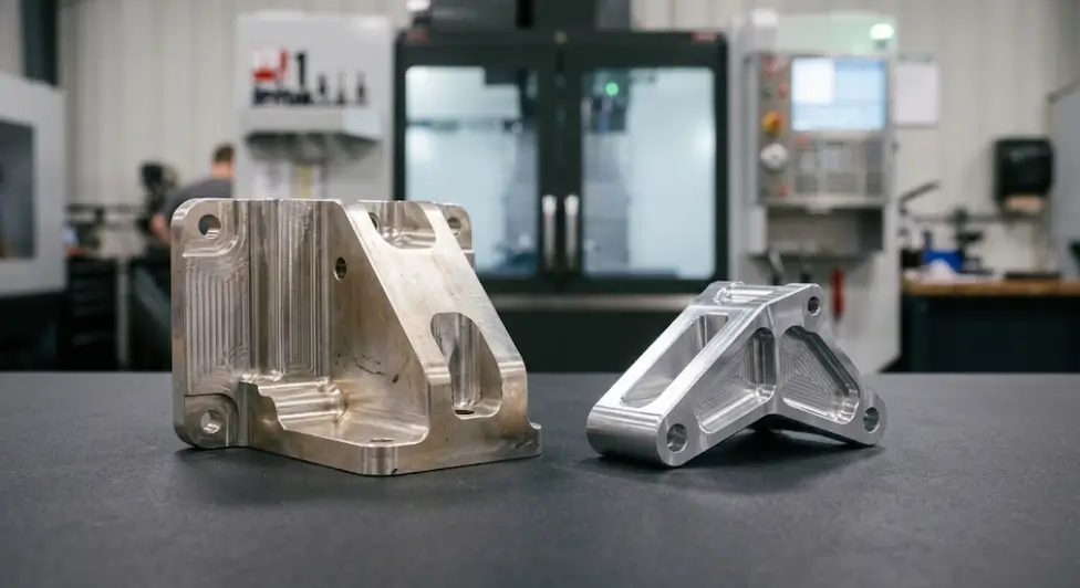
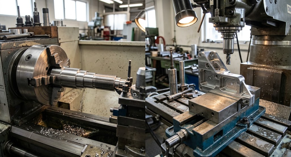
A cylindrical shaft with stepped diameters and a threaded end is a natural candidate for CNC turning. A mounting bracket with pockets, slots, and holes on several faces is more likely to need CNC milling.
Both processes remove material to produce precision components, but they approach the job differently. Choosing between them affects more than the machining method. It can influence setup time, tool access, dimensional consistency, material waste, and the cost of the finished part.
The most useful starting point is the geometry. Which features define the component? Are they arranged around a central axis, or spread across several faces? Does the part need flat pockets and slots, or mostly cylindrical surfaces?
Once those questions are answered, the manufacturing options become easier to evaluate.
Start with the Features, Not Just the Part's Overall Shape
Two components can look similar in size yet require very different machining strategies.
A spacer with a central bore and several outside diameters has relatively simple rotational geometry. A compact equipment housing might have a similar overall envelope, but its pockets, mounting holes, and flat reference surfaces make it a different manufacturing problem.
CNC turning is generally well suited to rotationally symmetric features. CNC milling is more versatile when a part contains non-cylindrical geometry, including pockets, slots, flat faces, and contours.
The distinction is not absolute. A turned part can have milled features, and a milled component can include cylindrical features. The question is which process can produce the main geometry efficiently and what additional operations are needed to complete the part.
When CNC Milling Is the Better Fit
In CNC milling, a rotating cutting tool removes material from a workpiece held by a fixture, vise, or other suitable workholding system. The programmed tool path creates the required surfaces and features.
Milling is commonly used for components such as:
- Mounting brackets with multiple holes and slots
- Equipment housings with recessed pockets
- Fixture plates with accurately positioned features
- Components with irregular outlines
- Parts with flat surfaces on several sides
Consider a mounting bracket with a large central pocket, four mounting holes, and two slots along one edge. The features have different orientations and do not follow one rotational axis. Milling provides a practical way to produce this geometry.
The main challenge is often tool access. A cutter needs sufficient clearance to reach the intended feature without colliding with surrounding walls or fixtures.
Deep pockets may require long tools, which can deflect under cutting forces. Narrow slots can limit cutter diameter and make material removal less efficient. Small internal corner radii may also require smaller cutters, potentially increasing machining time.
Designers can often improve manufacturability by allowing practical internal radii, avoiding unnecessarily deep cavities, and checking whether features can be reached from the planned setup. These decisions should preserve the component's functional requirements.
For more design considerations, see the CNC machining design guide.
When CNC Turning Makes More Sense
CNC turning is built around rotational motion. The workpiece spins while a cutting tool removes material from its outer diameter or, with suitable tooling, from internal surfaces.
This makes turning a natural choice for shafts, bushings, pins, spacers, cylindrical sleeves, and similar components.
Imagine a shaft with three diameter sections, two shoulders, a central bore, and a threaded end. Because the main features follow the same axis, turning can often produce them efficiently without repeatedly repositioning the part.
Turning is also useful for producing grooves and other rotational features. The exact operations depend on the machine configuration, tooling, and part design.
The process becomes more complicated when the component includes features away from the central axis. A cross-hole, keyway, or milled flat may require a secondary operation. That can mean moving the workpiece to another machine, securing it in a different fixture, and verifying alignment before machining continues.
For this reason, a part should not be classified as a turning job simply because its outside profile is cylindrical. The full set of features determines whether turning alone is sufficient.
CNC Milling vs. CNC Turning: A Practical Comparison
| Factor | CNC Milling | CNC Turning |
|---|---|---|
| Typical geometry | Prismatic, contoured, or irregular | Cylindrical or rotationally symmetric |
| Common features | Pockets, slots, flat faces, positioned holes | Diameters, shoulders, grooves, axial bores |
| Cutting motion | A rotating cutter removes material from the workpiece | The workpiece rotates against a cutting tool |
| Workholding | Fixtures, vises, clamps, or dedicated setups | Chucks, collets, or other suitable holding systems |
| Common challenge | Reaching features on different faces | Machining off-axis features or supporting long parts |
| Potential advantage | Complex features in different orientations | Multiple concentric features along one axis |
This comparison is a useful guide, but it does not establish a universal winner. Actual cost and performance depend on part dimensions, material, tolerances, machine configuration, and production quantity.
A simple cylindrical spacer will usually favor turning. A pocketed mounting plate will generally favor milling. A component that combines turned diameters with milled flats may need both processes.
What Actually Determines the Cost?
The cost difference between milling and turning is rarely explained by machine time alone. Setup, material removal, tooling, inspection, and secondary operations all contribute to the finished part's price.
Setup and Workholding
Every setup requires the workpiece to be positioned and secured. The manufacturer may also need to establish reference surfaces and verify alignment.
A housing with features on several faces may require multiple milling setups. A shaft with additional flats or cross-holes may need a separate milling operation after turning.
Reducing unnecessary setups can lower handling time and help maintain relationships between critical features. However, combining operations is only beneficial when the workpiece can still be held securely and the required accuracy can be achieved.
Material Removal and Tool Access
The starting stock size affects how much material must be removed. A component machined from a large block may require substantial cutting to create deep pockets. A rotational part made from appropriately sized bar stock may involve less waste, depending on its geometry.
Tool access can add further complexity. Deep cavities, narrow slots, and long cutting tools may require more conservative machining conditions. Long, slender turned parts can also deflect under cutting forces and may need additional support.
Where the application allows, revising a non-critical feature can simplify production. A practical corner radius or a less restrictive pocket depth may reduce machining effort without affecting function.
Tolerances and Inspection
Tighter tolerances can increase machining and inspection requirements. They should be specified where the component's function requires them, rather than applied to every dimension by default.
For example, a bearing seat may need close dimensional control because it determines fit and alignment. A non-functional external dimension may permit a wider tolerance.
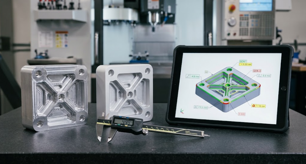
Drawings should clearly identify critical dimensions, datum references, and any geometric requirements that affect assembly. The CNC machining tolerances guide explains how tolerance choices influence manufacturing decisions.
Order Quantity
For prototypes and small batches, setup effort can have a substantial effect on unit cost. For larger production runs, repeat cycle time and process consistency may carry more weight.
A fair comparison should consider programming, tooling, machining, inspection, finishing, and expected repeat orders. The process with the shortest cutting time is not automatically the least expensive option overall.
Accuracy and Surface Finish Depend on the Application
Neither CNC milling nor CNC turning is inherently more accurate for every feature.
Turning is particularly useful when several diameters must remain concentric around a common axis. Milling is well suited to flat reference surfaces and features positioned relative to defined datums.
The achievable result depends on machine condition, tooling, material behavior, workholding, cutting parameters, and inspection methods. Geometry introduces additional challenges: thin-walled milled components may deform during machining, while long turned shafts may deflect under cutting forces.
Surface finish is equally dependent on the application. Tool geometry, feed rate, cutting conditions, vibration, and material all influence the result. Some surfaces may meet requirements directly after machining, while others need additional finishing.
If surface texture affects sealing, friction, appearance, or assembly, state the required finish on the engineering drawing. The CNC machining surface finishes guide provides further information on finish requirements and available options.
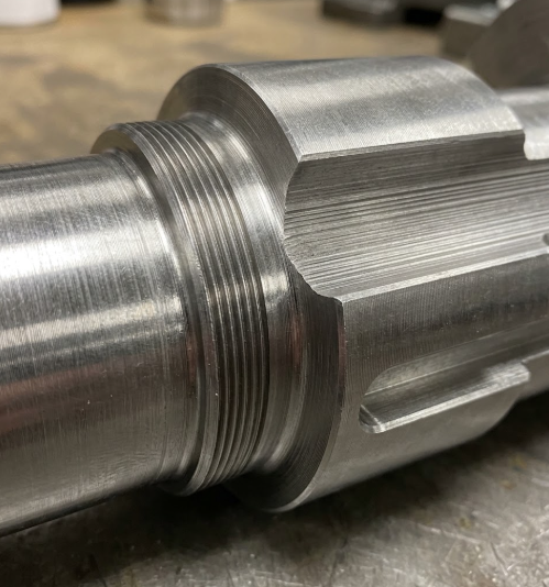
When a Part Needs Both Milling and Turning
Many components combine rotational geometry with features that cannot be produced efficiently by turning alone.
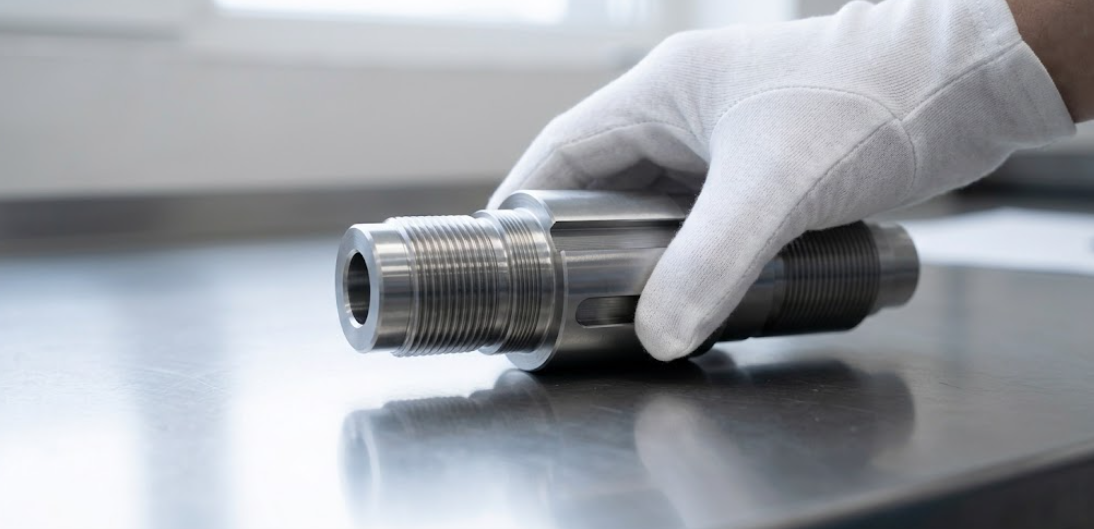
A shaft may need turned diameters and shoulders followed by milled flats. A cylindrical housing may require a turned outer surface and mounting holes. A connector may combine concentric features with slots positioned away from its central axis.
In these cases, the order of operations matters.
Turning may establish the primary diameters before milling creates the flats or slots. The manufacturer then needs to locate the component accurately for the secondary operation, especially when those features must align with another surface or dimension.
Before production, consider:
- Which surfaces will serve as datums for later operations?
- Will repositioning the component affect critical dimensions?
- Can the part be held securely during each operation?
- Are additional inspection steps needed to verify feature alignment?
- Would a combined machining setup be practical with the available equipment?
Some machine configurations can perform turning and milling in one setup, reducing handling. However, this depends on the supplier's actual equipment and process capabilities. It should be confirmed during quotation rather than assumed.
Design Details to Check Before Requesting a Quote
A CAD model can look straightforward while hiding features that complicate machining. Reviewing these details early can help avoid unnecessary costs and production delays.
- Internal corners: Standard milling cutters leave radiused internal corners. Allowing a practical radius can simplify tooling and reduce the need for specialized operations.
- Deep pockets and narrow slots: These features can restrict tool access and reduce cutter rigidity. If their dimensions are not functionally critical, reconsidering their proportions may improve manufacturability.
- Thin walls: Thin sections can vibrate or deform during material removal. The appropriate thickness depends on the material, geometry, unsupported span, and machining strategy.
- Features on multiple faces: Holes and pockets on different sides may require additional setups. Consider their positions relative to workholding and the dimensions that must remain aligned.
- Functional tolerances: Identify the dimensions that control fit, alignment, sealing, or performance. Avoid applying the tightest tolerance to every dimension by default.
- Material and finish requirements: Specify the material grade and any required surface treatment clearly. These choices can affect machining strategy, lead time, and total cost.
The objective is not to simplify the part at the expense of its function. It is to make the design practical to manufacture while retaining the features and performance that matter.
Conclusion
CNC milling and CNC turning solve different geometry problems. Milling is often the practical choice for pockets, slots, flat faces, and irregular profiles. Turning is particularly effective for shafts, bushings, and components with concentric features.
When a component combines both, the manufacturing sequence depends on tool access, workholding, datum relationships, and tolerance requirements. Material, surface finish, and production quantity also influence the final cost.
The best process is not necessarily the one with the fewest visible machining steps. It is the approach that produces the required geometry reliably, maintains critical dimensions, and avoids unnecessary operations.
If you have a drawing or 3D model ready, contact SelenPreci to discuss your CNC machining requirements and request a quotation.
Frequently Asked Questions
Is CNC milling more expensive than CNC turning?
Not always. Turning is often economical for parts dominated by cylindrical features, while milling is better suited to components with pockets, slots, and irregular profiles. Material, setup requirements, tolerances, and order quantity all affect the final price.
Can CNC turning produce flat surfaces or cross-holes?
These features may require milling or drilling as secondary operations. Some machine configurations can perform additional operations, but the available capabilities depend on the equipment and part design.
Which process is better for precision components?
Neither process is universally more precise. Turning is particularly suitable for concentric diameters, while milling can produce accurate flat surfaces and positioned features. The result depends on the component, setup, machining strategy, and inspection requirements.
Can one component use both CNC milling and CNC turning?
Yes. Many components combine turned diameters with milled flats, slots, or holes. The manufacturing sequence should account for workholding, datum references, and the relationship between critical features.
What information should I provide for a CNC machining quote?
Provide a 2D drawing or 3D CAD model, material specification, quantity, required tolerances, surface-finish requirements, and any post-processing needs. Identifying critical dimensions and the target delivery date also helps the manufacturer evaluate the project.
6061 Aluminum vs. 7075 Aluminum for CNC Machining
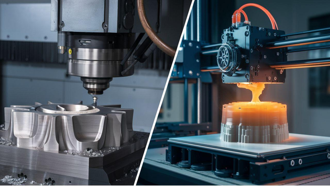
CNC Machining vs. 3D Printing: How to Choose