CNC Machining Design Guide: 8 Practical Tips
CNC Machining Design Guide: 8 Practical Tips for Better Parts
A CNC machined part can look straightforward in a CAD model and still present a few challenges during production. A pocket may be too deep for the available cutting tool. A thin wall may flex while material is being removed. Or a drawing may specify tight tolerances on dimensions that have little effect on the final assembly.
These are not unusual design issues. They often come down to details that are easy to overlook when the main focus is getting the geometry right.
Reviewing those details before requesting a quote can help avoid unnecessary machining work and drawing revisions. The aim is not to simplify every feature, but to make sure the design can be manufactured while still doing its job.
Here are eight areas worth checking before sending a part out for CNC machining.
1. Apply Tight Tolerances Only Where They Matter
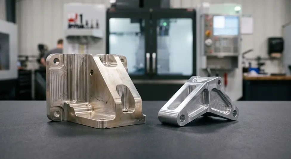
Take a mounting bracket with several holes. The positions of the holes that align the bracket with another component may be critical. The dimensions of an outer edge, on the other hand, might have little effect on assembly.
Giving both features the same tight tolerance may add inspection and manufacturing effort without providing a practical benefit.
Before specifying a tolerance, consider how the dimension is used. Does it control fit, alignment, movement, or sealing? Would a small variation cause a real problem? These questions help distinguish functional requirements from dimensions that simply look better with a smaller tolerance range.
Tolerances should still be realistic for the selected material, geometry, and manufacturing process. If a dimension is critical, make that clear on the engineering drawing rather than expecting the manufacturer to infer its importance.
For a closer look at this topic, read our guide to CNC machining tolerances.
2. Give Cutting Tools Enough Room to Reach the Feature
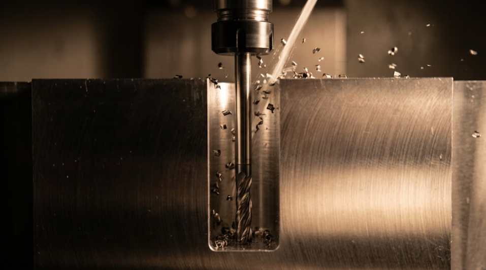
Deep pockets and narrow slots can be harder to machine than they appear in a CAD model. The cutting tool needs enough room to reach the material, remove chips, and operate without excessive deflection.
A long, slender tool may be necessary for a deep cavity, but it can be more susceptible to vibration. That may affect dimensional consistency and surface quality.
Where the part's function allows, consider widening a narrow pocket or reducing its depth. Internal corners should also be reviewed because standard milling cutters leave a radius rather than a perfectly sharp internal corner.
If a sharp corner is required for a mating component, discuss the requirement before finalizing the design. A small geometry change may solve the problem more economically than adding a secondary operation later.
Not every difficult feature can be redesigned, of course. The important thing is to identify it early so that a suitable machining approach can be evaluated.
3. Be Careful With Thin Walls
Thin walls are common in lightweight housings and compact components, but they can be difficult to machine reliably. Cutting forces may cause the material to flex, particularly when a wall is tall or poorly supported.
The risk depends on several factors, including material properties, wall height, geometry, and workholding. For this reason, a single minimum wall thickness should not be treated as a universal rule.
If a thin section is not essential, increasing its thickness may make the part easier to machine. If weight or available space is a major constraint, ribs or other structural features may be worth considering.
Any change needs to preserve the component's intended function. A thicker wall is not automatically better if it interferes with assembly or adds unwanted weight.
For a design with unusually thin sections, it is worth reviewing the geometry with the manufacturer before production.
4. Make Hole and Thread Requirements Clear
Holes are easy to add in CAD, but their manufacturing requirements can be different.
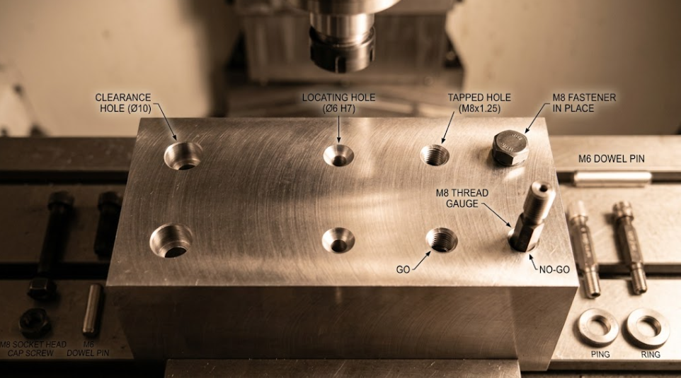
A clearance hole allows a fastener to pass through. A locating hole helps position one component relative to another. A tapped hole needs the correct thread specification and sufficient usable thread depth.
For threaded features, identify the thread size and standard. Where depth affects assembly, specify the required thread depth and clarify the total hole depth if necessary. This is particularly useful for blind holes, where the usable thread depth may be less than the drilled depth.
Also check how close holes sit to edges, pockets, and other features. Moving a hole slightly may improve tool access or leave more material around the feature.
The drawing should communicate the requirements that matter to assembly and function. Clear details reduce the chance of assumptions being made during manufacturing.
5. Choose Material for the Job, Not Just the Price
Material selection affects more than the purchase price. It influences weight, strength, corrosion resistance, machinability, and how the finished part behaves in service.
Aluminum is often considered for lightweight housings, brackets, and machined components. However, not all aluminum grades offer the same properties. The right grade depends on the loads, operating environment, and other requirements of the application.
Engineering plastics may be suitable when low weight, electrical insulation, or chemical resistance is important. Temperature, moisture, wear, and long-term loading should also be considered before making a selection.
A stronger or more expensive material is not automatically the better choice. The useful question is whether the material meets the actual requirements of the part.
If you are deciding between two commonly used aluminum grades, see Aluminum 6061 vs. 7075 for CNC Machining.
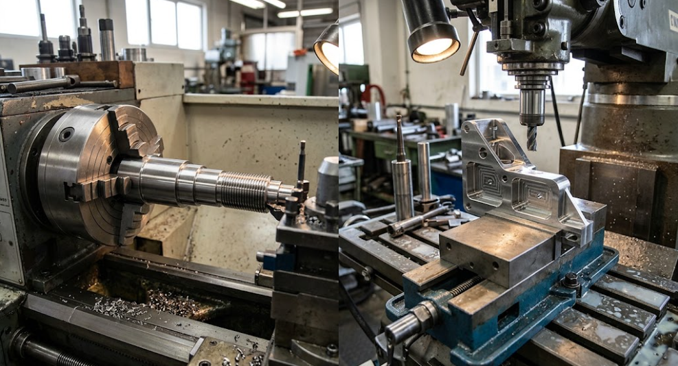
6. Think About How the Part Will Be Held During Machining
Part geometry affects how a component can be secured and positioned during machining. Features on several faces may require the workpiece to be repositioned, adding handling and alignment steps.
This matters when dimensions on different faces need to maintain a precise relationship. Each additional setup introduces another consideration for locating the part correctly.
During design, look at where the critical features are located and whether they can be accessed conveniently. Sometimes, adjusting the orientation of a feature can make machining more straightforward without changing its function.
There are limits to how much a design can be simplified. A complex part may genuinely require several operations. The goal is to avoid unnecessary setup difficulty, not to sacrifice a feature that the component needs.
7. Specify Surface Finish According to Function
A part's surfaces do not all serve the same purpose. An exterior face may be visible to a customer, while another surface may contact a seal, slide against a mating component, or receive a protective coating.
Those surfaces may need different finish requirements.
Start by identifying what the surface needs to do. Appearance, corrosion protection, friction, wear, and dimensional fit are separate considerations. A finish selected for one purpose may not address the others.
For example, if an aluminum component will be anodized, the finishing specification should be considered alongside any critical dimensions and fits. The relevant requirements depend on the process and the part's function.
Avoid using descriptions such as “smooth” when a measurable surface roughness requirement is important. State the applicable finish specification where necessary and identify the surfaces to which it applies.
Our guide to CNC machining surface finishes covers the main factors to consider.
8. Check the Drawing Package Before Requesting a Quote
A clear drawing package makes it easier for a manufacturer to understand what needs to be produced.
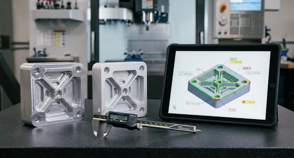
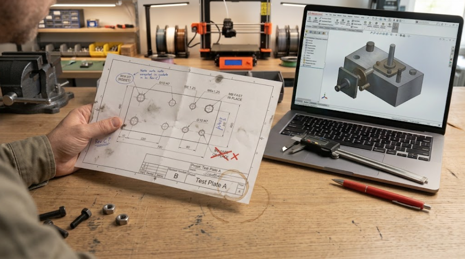
Before submitting your files, check that the CAD model and engineering drawing reflect the same revision. Confirm the material, quantity, critical dimensions, thread details, and surface finish requirements.
If a feature has a special inspection requirement, include it in the drawing or explain it in the quotation request. It can also help to describe the intended application when the reason for a particular requirement is not obvious from the geometry.
For example, telling the manufacturer that a face is used for alignment provides useful context for reviewing its dimensional requirements.
A complete quotation request does not need to be complicated. It simply needs enough information for the manufacturer to assess the part and identify any questions before production.
Use our CNC machining quote checklist before sending your files.
Frequently Asked Questions About CNC Machining Design
1. What should I consider when designing a part for CNC machining?
Start with the material, critical tolerances, tool access, wall thickness, and surface finish. Also consider how the part will be held during machining and how its important features will be inspected. The right priorities depend on the component's function and geometry.
2. How can I reduce CNC machining costs without compromising quality?
Review unnecessary tight tolerances, deep or narrow pockets, difficult internal corners, and avoidable machining setups. Material and finishing choices can also affect cost. Any design change should preserve the part's functional and quality requirements.
3. What tolerances should I specify for CNC machining?
There is no single tolerance that suits every feature. Requirements depend on the geometry, material, manufacturing process, and intended fit. Specify tighter tolerances where dimensions affect function and use appropriate general tolerances for non-critical features.
4. What files are needed for a CNC machining quote?
A 3D CAD model and a dimensioned engineering drawing are a useful starting point. Include material, quantity, critical dimensions, tolerances, thread details, and finishing requirements. Confirm the accepted file formats with your manufacturer before submitting the package.
Final Thoughts
Good CNC machining design comes down to understanding the relationship between a part's function and the work required to manufacture it.
Tight tolerances need a reason. Deep pockets and thin walls deserve attention before production. Material and surface finish requirements should reflect the component's actual operating conditions.
Reviewing these details early will not remove every manufacturing challenge, but it can help identify problems while changes are still manageable.
Have a Part Ready for Review?
If you are preparing a CNC machined component, gather your CAD model, engineering drawing, material requirements, quantity, and target delivery date.
Contact SelenPreci to discuss your project and the information needed for a manufacturing review.
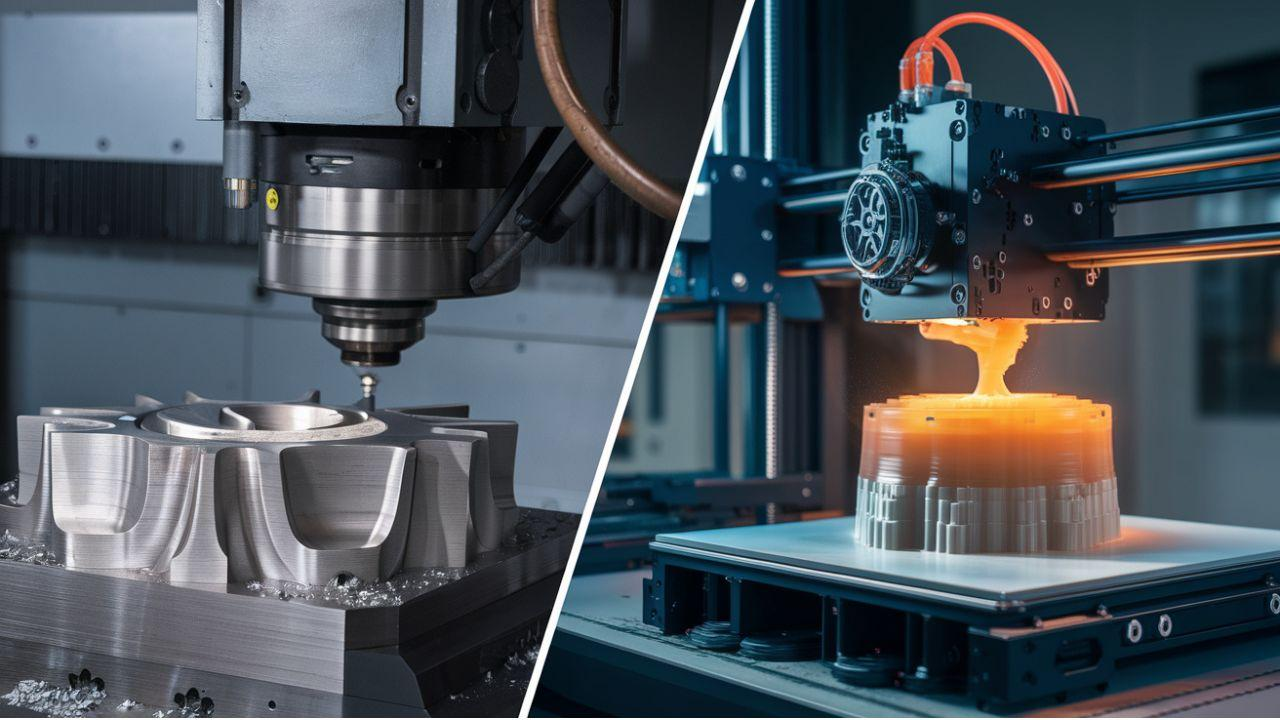
CNC Machining vs. 3D Printing: How to Choose